Solar Geometry, Tilt, and Azimuth: Optimizing PV System Orientation for Maximum Energy Yield
The performance of a solar photovoltaic (PV) system is governed not only by module efficiency and system components, but also by how the system is physically oriented relative to the sun. Solar geometry — the relationship between the sun’s position and the solar module — plays a central role in determining how much solar radiation is intercepted by the array and converted into electricity.
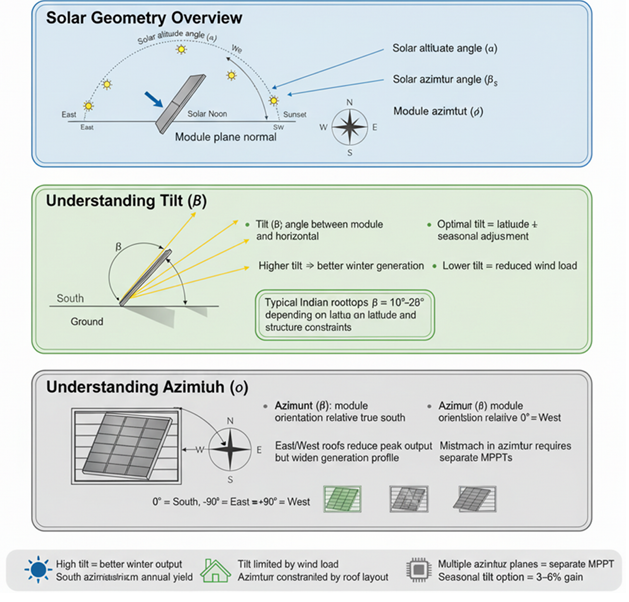
The attached diagram provides a structured overview of three foundational concepts in PV system design: solar geometry, module tilt, and module azimuth. Together, these parameters define how effectively a solar array captures sunlight throughout the day and across seasons. Understanding and optimizing these factors is essential for engineers, installers, facility managers, and building owners seeking to maximize annual energy yield and ensure reliable system performance.
This article explains each section of the diagram and translates these concepts into practical design guidance.
1. Solar Geometry: Understanding the Sun’s Path
Solar geometry describes the apparent movement of the sun across the sky relative to a fixed point on Earth. Because Earth’s axis is tilted and its orbit is elliptical, the sun’s position changes by:
- Time of day
- Day of the year (season)
- Geographic latitude
The diagram highlights two key solar angles:
Solar Altitude Angle (α)
The solar altitude angle (α) is the vertical angle between the sun and the horizontal plane. In simple terms, it indicates how high the sun is in the sky.
Key characteristics:
- Low in the early morning and late evening
- Highest at solar noon
- Higher in summer and lower in winter (for most locations)
A higher solar altitude generally means stronger solar irradiance on horizontal and moderately tilted surfaces, while a low solar altitude increases shading risks and reduces effective irradiance.
Solar Azimuth Angle (βₛ)
The solar azimuth angle (βₛ) defines the horizontal direction of the sun relative to true south (or true north, depending on convention). It describes whether the sun is positioned toward the east or west at a given time.
Solar azimuth is important for:
- Determining morning vs. afternoon production
- Evaluating shading from nearby obstructions
- Designing east-west oriented arrays
Together, solar altitude and solar azimuth define the sun’s instantaneous position and determine how directly sunlight strikes the module surface.
2. Module Plane Normal and Angle of Incidence
The diagram also introduces the concept of the module plane normal, which is an imaginary line perpendicular to the surface of the solar panel. Maximum energy is captured when sunlight arrives perpendicular to the module surface (i.e., when the sun’s rays are aligned with the module plane normal).
The angle between the incoming sunlight and the module plane normal is called the angle of incidence. As this angle increases:
- Effective irradiance on the module decreases
- Reflection losses increase
- Overall power output is reduced
Good system design aims to minimize the average angle of incidence over the year for the target production profile.
3. Understanding Tilt (β): Vertical Orientation
What Is Tilt?
Tilt (β) is the angle between the solar module and the horizontal plane. It determines how steeply the panel is inclined.
The diagram shows tilt as a critical parameter affecting seasonal energy capture and system performance.
Why Tilt Matters
Tilt directly influences:
- Annual energy yield
- Seasonal energy balance (summer vs. winter)
- Self-cleaning from rain (dust and soiling)
- Structural and wind loading
Optimal Tilt Angle
A common engineering rule of thumb is:
Optimal tilt ≈ Latitude ± seasonal adjustment
For example:
- For maximum annual energy: tilt ≈ local latitude
- For winter-optimized production: tilt = latitude + 10° to 15°
- For summer-optimized production: tilt = latitude − 10° to 15°
The diagram notes that in typical Indian rooftop installations, tilt angles often range from 10° to 28°, depending on:
- Latitude
- Roof slope
- Structural constraints
- Wind load considerations
Trade-Offs in Tilt Selection
The diagram highlights key trade-offs:
- Higher tilt = better winter generation
- Lower tilt = reduced wind load and structural stress
Steeper tilt angles improve low-sun-angle performance in winter but increase wind forces and may reduce summer output slightly. Lower tilt angles reduce wind loads and may be necessary for flat roofs, but they can reduce winter energy yield and increase soiling accumulation.
4. Understanding Azimuth (θ): Horizontal Orientation
What Is Azimuth?
Azimuth (θ) defines the horizontal orientation of the solar module relative to true south (in the Northern Hemisphere) or true north (in the Southern Hemisphere).
The diagram uses the following convention:
- 0° = South
- −90° = East
- +90° = West
Why Azimuth Matters
Azimuth affects:
- Timing of energy production (morning vs. afternoon)
- Total annual yield
- Alignment with building load profiles
- Grid export vs. self-consumption patterns
South-Facing Orientation
In the Northern Hemisphere, a true south-facing array (0° azimuth) generally maximizes annual energy production. This orientation balances morning and afternoon output and aligns well with peak solar altitude around midday.
East-West Orientation
The diagram notes that east-west roofs reduce peak output but widen the generation profile. This configuration has several practical advantages:
- More uniform production throughout the day
- Better alignment with morning and afternoon building loads
- Reduced midday peak clipping
- Improved self-consumption in commercial buildings
East-facing arrays produce more energy in the morning, while west-facing arrays produce more in the afternoon.
Mismatch in Azimuth and MPPT Implications
The diagram also highlights an important electrical design consideration:
Mismatch in azimuth requires separate MPPTs
When different array sections face different directions (e.g., east and west), they should be connected to separate Maximum Power Point Trackers (MPPTs) or inverters. This prevents electrical mismatch losses and ensures each array operates at its optimal voltage and current point.
5. Practical Constraints: Roof Layout and Wind Loads
In real-world projects, ideal tilt and azimuth are often constrained by:
- Roof orientation and geometry
- Structural capacity
- Wind load limits
- Setback and fire access requirements
- Aesthetic or architectural considerations
The diagram emphasizes that:
- Tilt may be limited by wind load
- Azimuth may be constrained by roof layout
As a result, system designers must balance theoretical optimums with practical feasibility.
6. Seasonal Tilt Adjustments
The diagram also notes that seasonal tilt options can provide a 3–6% gain in energy yield. In adjustable or ground-mounted systems, changing tilt seasonally can:
- Increase winter production with steeper tilt
- Increase summer production with flatter tilt
However, for most rooftop systems, fixed tilt is used due to:
- Mechanical complexity
- Maintenance requirements
- Cost-benefit considerations
Seasonal adjustment is more common in off-grid or small ground-mounted systems where maximizing energy yield is critical.
7. Implications for System Design and Energy Modeling
Accurate modeling of tilt and azimuth is essential for:
- Energy yield simulations (PVsyst, Helioscope, SAM, etc.)
- Financial projections
- Performance guarantees
- LEED, net-zero, and sustainability reporting
Small deviations from optimal orientation can result in:
- 2% to 10% reductions in annual energy yield
- Shifts in production timing
- Increased mismatch and electrical losses
For large portfolios or campuses, even small percentage losses can translate into significant absolute energy and revenue impacts.
Conclusion
The attached diagram provides a concise but technically rich overview of how solar geometry, tilt, and azimuth define the foundation of PV system performance. While high-efficiency modules and inverters are important, the physical orientation of the array ultimately determines how much sunlight is captured in the first place.
By understanding solar altitude, solar azimuth, tilt, and module orientation, project stakeholders can make informed decisions that balance energy yield, structural constraints, and operational goals. Optimizing these parameters is one of the most cost-effective ways to improve system performance — often requiring no additional equipment, only better design.
In solar PV, good geometry is good economics.