An effective earthing system is only as good as its measured resistance. In solar photovoltaic (PV) installations, earth resistance testing is a mandatory commissioning and maintenance activity that verifies whether fault currents can safely dissipate into the ground. The image illustrates the three-point fall-of-potential method, the most widely accepted technique for measuring earth resistance in accordance with electrical standards and good engineering practice.
1. Why Earth Resistance Testing Is Essential
Earthing provides a low-resistance path for:
- Fault and leakage currents
- Lightning-induced surges
- Transient overvoltages
If earth resistance is too high, protective devices may not operate correctly, leading to:
- Electric shock hazards
- Equipment damage
- Fire risk
- Non-compliance during inspection
Regular earth resistance testing ensures the earthing system continues to perform as designed.
2. Overview of the Three-Point Fall-of-Potential Method
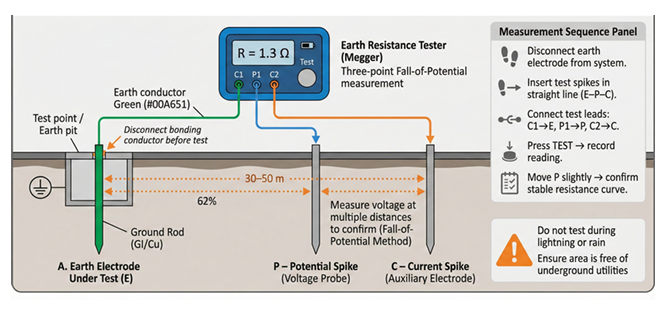
The illustrated setup uses:
- E – Earth electrode under test
- P – Potential spike (voltage probe)
- C – Current spike (auxiliary electrode)
An earth resistance tester (megger) injects a test current through the earth electrode and auxiliary current spike, then measures the resulting voltage at the potential spike to calculate resistance using Ohm’s law.
3. Test Layout and Electrode Spacing
Correct spacing is critical for accurate results:
- The current spike (C) is placed typically 30–50 meters away from the earth electrode under test.
- The potential spike (P) is positioned at approximately 62% of the distance between E and C.
This 62% rule helps ensure the measured resistance represents the true earth electrode resistance without interference from overlapping resistance zones.
4. Test Connections and Instrument Setup
The earth resistance tester has dedicated terminals:
- C1 and C2 – current circuit
- P1 and P2 – potential circuit
The connection sequence shown ensures proper current injection and voltage measurement. Test leads must be intact, properly insulated, and firmly connected to avoid erroneous readings.
5. Measurement Sequence and Best Practices
The recommended testing sequence includes:
- Disconnect the earth electrode from the system bonding conductor
- Insert current and potential spikes in a straight line
- Connect test leads as per tester markings
- Press the test button and record the resistance value
- Slightly move the potential spike and repeat measurement to confirm curve stability
A stable resistance curve confirms accurate test conditions.
6. Interpreting Earth Resistance Values
Typical acceptable earth resistance values depend on standards and application:
- Solar PV systems often target ≤ 1–2 ohms
- Critical installations may require even lower values
If resistance exceeds acceptable limits, corrective actions may include:
- Adding parallel earth electrodes
- Improving soil conductivity using charcoal or bentonite
- Increasing electrode depth or number
7. Safety Precautions During Testing
The image highlights key safety warnings:
- Do not test during lightning or rain
- Ensure the area is free of underground utilities
- Use appropriate PPE
- Isolate the earth electrode from live systems
Ignoring these precautions can endanger personnel and invalidate test results.
8. Documentation and Compliance
Test results must be:
- Recorded during commissioning
- Included in handover documentation
- Re-tested annually or as per O&M schedules
Electrical inspectors often request earth resistance test reports as part of statutory approval.
9. Role in Solar PV Operations and Maintenance
Over time, soil conditions change due to:
- Seasonal moisture variation
- Corrosion of electrodes
- Construction activity
Regular testing ensures early detection of degradation and sustained system safety.
Conclusion
Earth resistance testing is a fundamental verification step in solar PV system safety. By applying the three-point fall-of-potential method correctly, system owners and operators can confirm the effectiveness of the earthing network, ensure compliance with standards, and protect both people and equipment. Routine testing, proper documentation, and corrective action when required are essential elements of responsible solar PV operation.